Little update.
There are two main pcb boards in inverter assembly. One with car connector. Second one, igbt transistors driver, connected to previous.
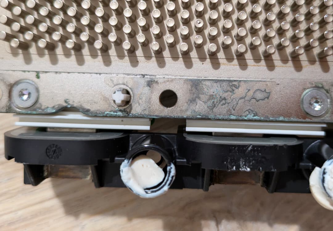
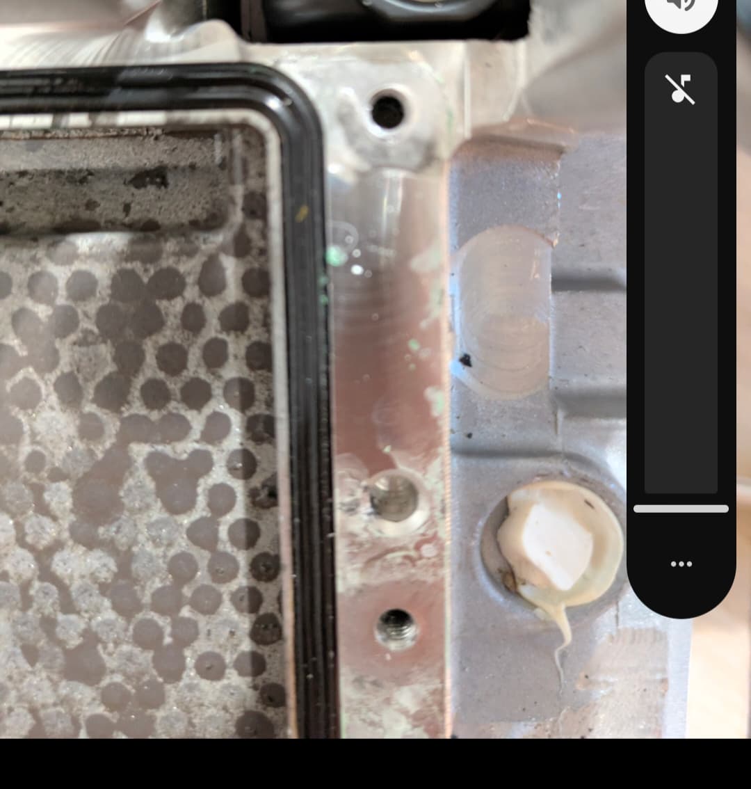
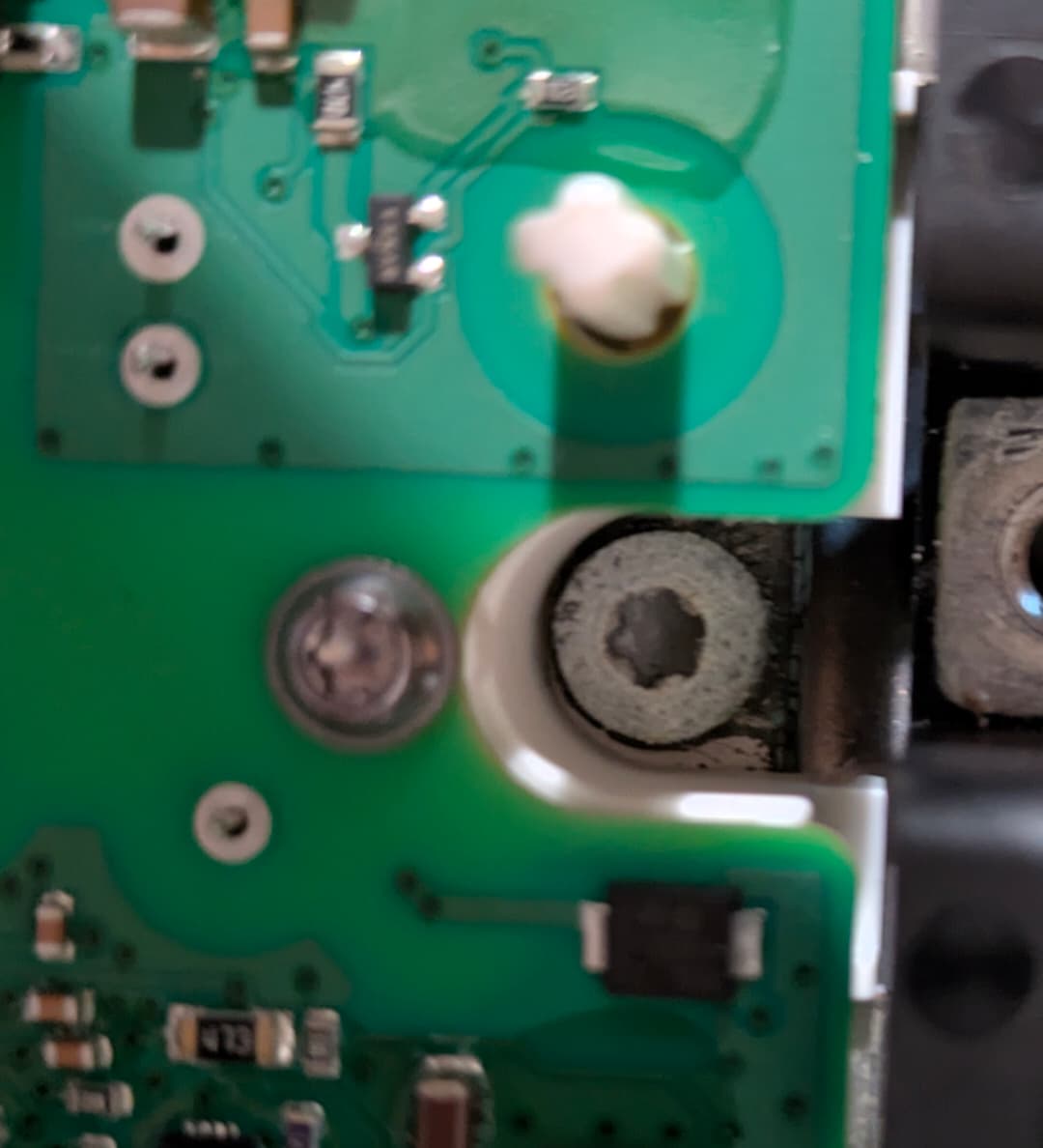
I checked boards and found small coolant leak, between igbt driver heatsink and coollant compartment. There are also signs of corrosion.
So, most likely due to the moisture environment something on igbt driver pcb blown, but there is a lot of protection which immediately turns off the power supply to this board. So finding out what’s broken isn’t easy.
I think, I will buy another used inverter assembly and try to swap igbt driver board from it.
It could be that my main ecu board is still fine, so I won’t need immo codes procedure
I will keep you posted.
I was able to track down the main issue in the ECU and after connecting to Diagbox, I could successfully clear the faults.
Long story short:
What I found? Bad electrolytic capacitors and two failed voltage regulators, all on the main PCB. Now I have to order the proper parts and assemble everything back to fully check it.
My current hypothesis is that everything is related to a corrosive environment—most likely due to a coolant leak—and a lack of proper protection on one chip. This could have led to a current leakage that, in turn, overloaded the regulators.
Long story:
At first, I focused on the unstable power, which I could hear as a clicking noise in one of the voltage regulators. Changing one electrolytic capacitor fixed this specific issue.
Despite the fix, the ECU still showed the same errors. So, I started looking at the signals driving the IGBT board. This board has 6 IGBT transistor drivers, each with a low-voltage (5V) side, and a PWM signal which drives regulators and transformers on the high-voltage (15V) side. The drivers are grouped into 3 banks for driving the low and high side of the motor switching. Each group also has a separate 5V supply from the main PCB.
The low and high voltage of the driver is supervised by a BM6104 chip, which pulls the FLT pin low if something is wrong.
I measured what the PWM signal should look like. When I powered up the board directly with 5V and applied this PWM, everything looked OK. The FLT pin stayed high, meaning each supervisor didn’t detect a problem.
Since the IGBT board seemed fine, I looked at the signals between boards. I previously found one PWM signal and thought it was a safety measure to prevent the ECU from driving both IGBT sides simultaneously without all connections.
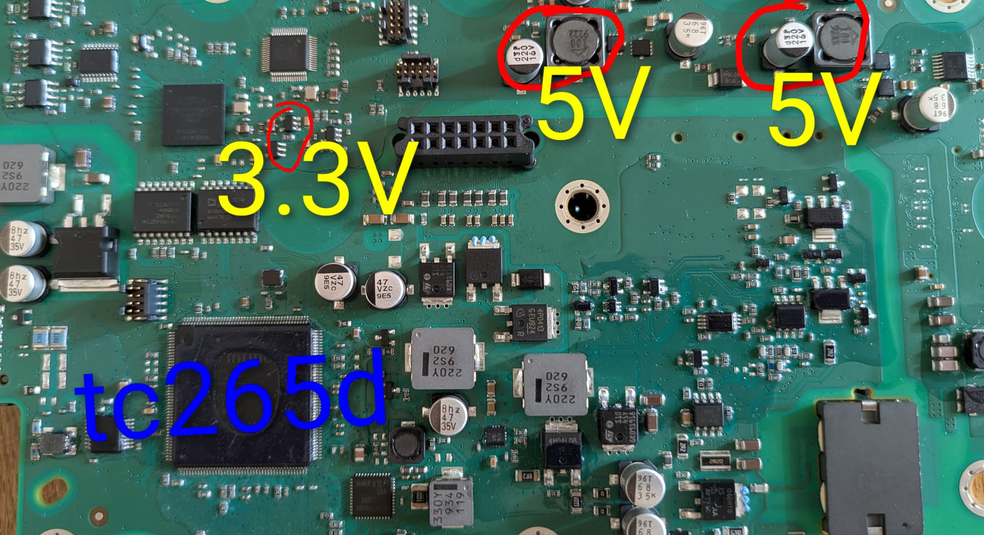
That’s when I realized the Altera fpga chip didn’t show any signs of life. It turned out the 1.2V I initially measured on the PCB was wrong. That line should have been 3.3V! The component marking , phu1, tracked down to a TPS7933 LDO.
Next to it, there was the same LDO, which I measured at… 5V! Pure luck that it didn’t fry the FPGA.
I desoldered both LDOs, hooked up an LDO I already had, and the ECU started up fully!
I’ve put car together during weekend and issues related to electric drive are fixed. I drove in full eletric and sport mode without problems. Energy recuperating is also working. There aren’t faults in diagbox afterwards.
What’s odd, ecu still shows different 12V battery voltage, but I suspect it takes measurment from small battery BMS, as it also shows similar values. I have to check BMS, as earlier it had blown fuse. I suspect that maybe someone was messing with small battery and touched frame, and since main battery is connected to small, it most likely blew fuse, but you never know.
Now, I have only TPMS light on dash and diagbox show tyres incompatible, but it’s looks like it is not related.
Well I’m really impressed you finally got it all back together fault free, I bet the main dealers would struggle with that.
Anyway, if the info in the ECU is correct, check the rolling diameter of each wheel. I had C5 X7, that would not change up when cornering at speed. After a lot of research, i decided to check the tyres on the back and found they were not the same MAKE.
I measured tyre circumferences with a flexible tape and found that one was 15mm longer than the other, so that was about 5mm larger on diameter!
Anyway, two new tyres on the back, perfect. It seems the ABS/Traction control ECU thought the car was skidding so, i suppose for safety it withheld the change-up command.
So - Just because the sizes on the tyres are the same, it doesn’t mean they are all the same size, manufacturering tolerances and all.