DS 7 RMCU_PHEV issue

Hello,

I recently purchased this DS 7 E-Tense knowing it had an electrical issue. Moving into this vehicle from my 2014 CX-5 is an incredible step—it feels like changing planets! I’m genuinely impressed with the design and technology; it’s a fantastic-looking vehicle.

For me, this project is a hobby—a kind of gamble on a car that I can fix in my spare time! The good news is the car can drive, but there’s a significant warning indicating that electric drive is not possible.

So, I started investigating. The first thing I found was a blown 125A fuse in the trunk, which connects to the secondary battery. It looked like no one had been there before, which I took as a potentially good sign. I replaced this fuse and both 12V batteries (as I’d read that weak batteries can cause such errors). The fuse didn’t blow again, and the car’s condition is the same as it was before the electric drive issue. My theory is that it was a sort of “dead main battery” scenario, and on starting, a large current draw from the secondary battery might have blown the fuse.

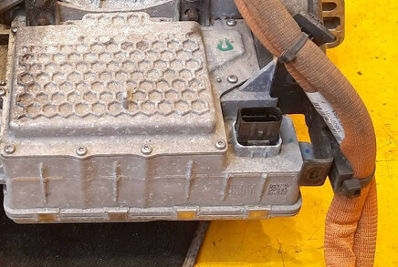
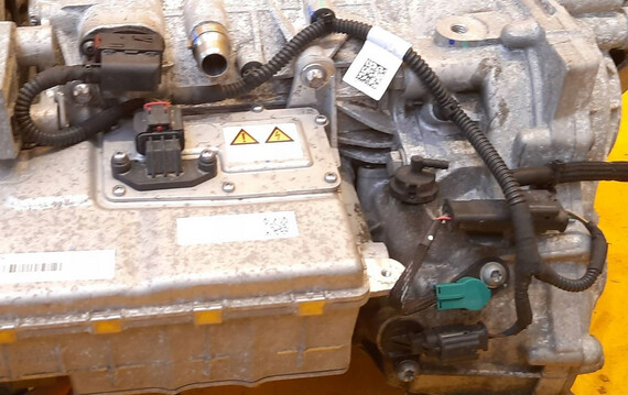
During this time, I was trying to use a standard OBD2 scanner for fault clearing, but it couldn’t do the job, so I ordered a PSA cable for DiagBox. I scanned the car, and there were about 25 faults, mainly attributed to a lack of power. I cleared what I could, and I’ve now narrowed the problem down to the RMCU_PHEV (Rear Motor Control Unit – Plug-in Hybrid Electric Vehicle).

There are hard faults for three temperature sensors indicating a short circuit to ground:
Fault Code Description
P11D9 Rear Electric Drive Temp Sensor Short Circuit to Earth
P11DB Rear Electric Drive Machine ECU Temp Sensor Short Circuit to Earth
P11DD Rear Electric Drive Inverter Temp Sensor Short Circuit to Earth

When reading standard parameters in DiagBox, I noticed that the voltage read by the module is around ∼10V, while the actual voltage is 12.5V.

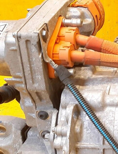
This voltage discrepancy could be due to the shorted sensors causing a voltage drop, or perhaps a wiring harness issue. It’s possible that insulation degraded during the event that blew the 125A fuse. This seems more likely to me since three different temperature sensors in three different locations are showing the same short-to-ground fault.

It would be significantly easier if Stellantis wouldn’t restrict access to official repair manuals, as finding documentation is very difficult. I purchased Haynes Autofix, but it contains nothing important for this specific module or fault.

Does anyone know where I might source such documentation? Is it available through services like Autodata?

BR

1 Like

You can’t access the DS service unless you have authorization an payment.

I’ll try to get something, but it may take a few days.

I don’t know if Autodata has it.

Thank you very much for your interest.

I have also update about car. Yesterday I was able to start it, but today not. I see pretty much same faults in diagbox, but when I press start engine, I see/hear that crank should occur, but it doesn’t.
Edit. I think difference is lost communication with ac compressor. I don’t think this fault was before. I will go thru fuses and connectors.

Also today I disassembled rear seat. If anyone will be interested in the future, you have to pull firmly on front to release 3 holders. After that you have to push seat towards back and pull up from side to release it from two holders on back of it.

So now, I have access to main HV battery connectors. These compartment looks pretty ugly, a lot of dust and debris. But there aren’t any faults from battery., so that should not be a problem. Also under seat are 3 multi pin connectors.

First thing tomorrow will be to push somehow car into garage. Then I will try to follow secondary battery cables and maybe disassemble rear inverter/motor.

BR

Since three sensors have the same error, they couldn’t all have failed at the same time. Check the ground wires to the body in the rear electrical engine harness. These wires are always green with a yellow ribbon. Only the green wires are ground wires, but not to the body. The colors of the other wires are random.
Also check the wires of these three sensors. Are they reaching the module connector?

I looked around on body ground points and clean all which are on down side. Measuring one which connects to inverter body it had around 15ohm. After that I chcecked diagbox and it still shows voltage difference. I didn’t have a lot of time today, so I didn’t disassemble a lot on back to get better access.

Also I looked around why car stopped starting, and immobilser error from hybird ecu appers
B1807 87 - fault with unlocking of the immobilser by the hybrid management ECU1
I think that maybe I screwed up this, because I tried repair/replace procedure in diagbox for rmcu_phev. There was information about writing codes from bsi. I didn’t perform it, I went back when there was information about keeping some kind of code on note, but maybe it already cleared current code from ecu. It will be stupid, but possible. Or maybe communication lines are unstable.
I will keep you posted.

BR

Good luck with your ‘Little’ Project, but have had Citroën (never DS) for 40+ years, getting to the bottom will be to say the least interesting. But I agree with @Andrew_PL it’s odd that all three senesors have errored at the same time so I would be looking at the common feed, either main fusebox or a return. Quite often one sensor will feed another then another, which in turn could pick a feed/signal from a random source. The sensors are probably variable, so you could you set up a test on a bench (secure them above a controllerable heat source - 60watt bulb) and make sure the sensors actually send out the signals they should as they get hotter the resistance will drop. Idealy you would need an oscilloscope but a good multimeter may do the job.

The small 12V battery powers the electric motors. If the battery shorted and the 125A fuse blew, it could have damaged the wiring harness before the fuse blew. This is a more optimistic scenario. The second scenario is a failure of the RMCU_PHEV module or another module related to the rear motor.

Thanks for your suggestions and input. For now I went thru fuses under the hood (also behind main ecu) and all where fine. I have to check fuses under steering wheel, but this is pain in the ass job.
Also looking online on similar assembly inverter/motor, it looks to me that there is only on 5 wires cable going out, it is kind of accessible from down. This is connector


I think it will be 4 wires for CANL/CANH/GND/Power and maybe battery sense voltage. I will have to somehow unplug it to check if insulation is okay.

There are few cables on top, but those are directly connected between inverter and motor. Also these on right can be temp sensors.

So, most likely inverter temp sensor is embedded into assembly.

I cleaned this ground connection, but not a lot changed

Edit. I played around. When I disconnect secondary battery, car starts and after 15s dies off. I’m on fuses under steering wheel, and I must say that someone creative had to design it :smiling_face_with_tear:
Also when I disconnected rear battery I got faults from few components, and somewhere must be distribution box for those ones.

BR

Small update from my journey.
I was able to get some schematic and I have idea what is going on.
I think, 90% chance it is failling rmcu ecu, but I also see that secondary bms reads 2v less than should. According to schematic there is direct connection between rmcu, and main and second bms.
I also made more obstacles since most likely starting replacement procedure blocked rmcu immo, since my version of diagbox wanted to connect to psa server for pin code, that obviously failed, and that I think locked ecu. So first I have to somehow return too previous state (ecu has to be cloned) either finding diagbox version with manual pin code or official coding by someone.

BR

Perform the procedure in Diagbox to replace both 12V batteries. This may allow both BMS systems to read the battery status correctly. If not, both BMS need to be replaced.
The PIN code is unique to each car, so you can’t clone it from another ECU.
There is also a problem with the traction battery serial number probably entered into the RMCU.

Do you know how this procedure for battery change is called? I can’t find it in diagbox. I tried bsi reset, but nothing changed.
Regarding cloning, I thought about cloning my current ecu to spare. Now it shows ecu locked, immo status “after sales”. I’m on 99% sure that I broked it by running replacement procedure which failed and somehow locked it. Even though it had proper keys inside and you couldn’t change it.

BR

You must always have a immo PIN. It doesn’t matter if it’s entered.

I’m back to begining. Doing procedure in official way restore ecu immo state. Car can start now.
I had 307 and used older version of diagbox, and didn’t know how much changed and how much carefull you have to be now.

Now I can focus on wires.

BR

Unfortunately, I suspect your problem is with the RMCU (internal). Checking the cables is probably a waste of time, as they’re likely fine. But it wouldn’t hurt to check it first.

I agree.
I have to disassemble it anyway so after getting better access I can check wires.
When there was foggy day I saw few others errors. We will see.

BR

Little update from my side.
I’m on disassembling rear of car to get access to rear motor. It looks like it will be possible to pull out motor without removing rear subframe. I thought about getting access to inverter from front, but it will require removing fuel tank and axles (they block access to inverter bolts).
And one question, maybe someone can tell. There is coolant reservoir close to charge cable connector (hidden behind cover), I think this is cooling for battery, and what else? When I was removing charger and discharging coolant pipes, color of coolant was completly different. In reservoir is blue, from charger it was yellowish. So, I’m wondering if charger and rear motor are cooled in ''normal" system. Or maybe there is somewhere blockage which cause rear motor to overheat and it changed coolant color.

BR

The rear electric motor and traction battery have separate cooling systems. The fluid should be the same color as the front fluid. Someone probably already repaired something there and used a different fluid.

Ok, that’s make sense. So it will be 3 colling circuts. I found that fuild should be compilant with PSA B71 5110, and found some online but none had such yellowish color. So, it is possible that someone was there, maybe add more water instead fluid.
Do you maybe know where to look for third reservoir?

BR

In my opinion, there should only be two circuits. One in the front for both engines and the gearbox. The second for the rear.

Looks like front, rear motor and charger are connected to main resovior, but they have separate pump circut. At least underneath transmission there is something like pump. When I opened main resovior coolant started pouring from disconnected pipes on back.

I pulled axles, and on long one bearing is gone. Like really bad gone :slightly_smiling_face: so thing to keep in mind if someone hear some noise on back.

I also almost pulled rear motor, it’s comming easily, but you have to be careful with wires/pipes.

Edit.
I pulled motor, at first I thought I was lucky because first sensor connector (black in previous post) which I checked was “quite” shorted 3ohm. I think this is temperature sensor for differential, and obviously it is not good. After looking on board it is more like clutch driver, since it have quite big transistors on lines which go to this connector.
Whats surprising when you unscrew it there is next connector from which wires go down, so to change it you have to open side cover to get access to differential. I disconnected this sensor and connected motor back to car, but result is same. Later on I disconnected all connectors, and ecu still measures 9.5V, so something is blown internally. I pulled pcb from it, at first visual inspection there is nothing really bad. I will try to measure it, maybe will find something.

BR